
If you want to reduce costs of manufacture, consider redesigning your machine brackets. You can do this by changing the brackets material or the way they are manufactured, or changing the load path.
Most machine brackets are either cast iron or welded steel. A quick comparison of material properties shows that for equal strength, steel sections can be 25% of the size of cast iron sections. For equal stiffness, steel sections can generally be 50% of the thickness of cast iron sections.
As weld metal is expensive, welded bracket designs push ahead of cast designs only when the amount of welding can be kept to a minimum, and high-speed downhand fillet welds are used. In many cases, components can be profiled or sheared from relatively thin sheet and bent to shape to reduce parts and weight. Thickness can easily be added where needed. Casting limitations on thicknesses and draft angles can often result in heavier components than their welded counterparts.
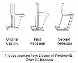
As with any design, it is not a one-rule-fits-all situation. Depending on the production numbers involved, aesthetics, amount of welding, weight, part complexity, and the dimensional accuracy required, both cast and welded brackets have their place.
To ensure that the modified bracket performs to the same level or better than the original, a comparative analysis was run.
This example shows the improvements made in redesigning a simple cast bracket as a welded bracket.
Results of Comparative Analysis
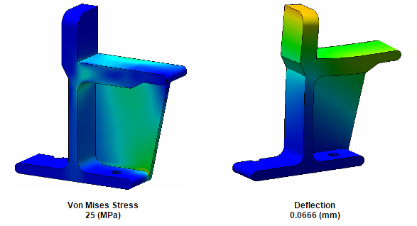
A cast bracket, made from Gray Cast Iron, was redesigned as a welded mild steel bracket. To check that this is as strong or stronger than the original, a comparative analysis was run. A vertical load of 10kN was applied to the bracket face. Making use of symmetry this was halved to 5kN. The bottom face of the bracket was restrained vertically, and a side restraint added at the corner to completely restrain the model. Note that a comparative analysis avoids the need to determine the effect of the supporting mounting face and contact conditions, etc.
Original Cast Bracket
Welded Bracket 1

Welded Bracket 2

Results
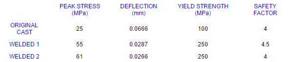
The stress plots show that the highest stresses in both the cast and first welded design occur at the gusset transition into the bottom plate. The stresses at these internal corners are re-entrant stresses, and therefore do not converge (because they are dependant on the mesh size). So analysing these would be a challenge. This could potentially cause problems, as weld quality at the weld toe is often inconsistent and a cause of stress concentrations. Simple redesign however minimises the need to analyse these areas.
The second welded bracket design moves the maximum weld stress from the weld toe into the length of the fillet weld, removing the peak stress at the gusset transition. It also gives a comparable factor of safety, with no tooling or patterns required and it is easily fabricated from two parts. The deflections are also smaller.
Note that the weld stresses in the above analyses will need checking with hand calculations to ensure they won’t be a problem, but the second welded bracket is clearly better than the first for weld stresses.